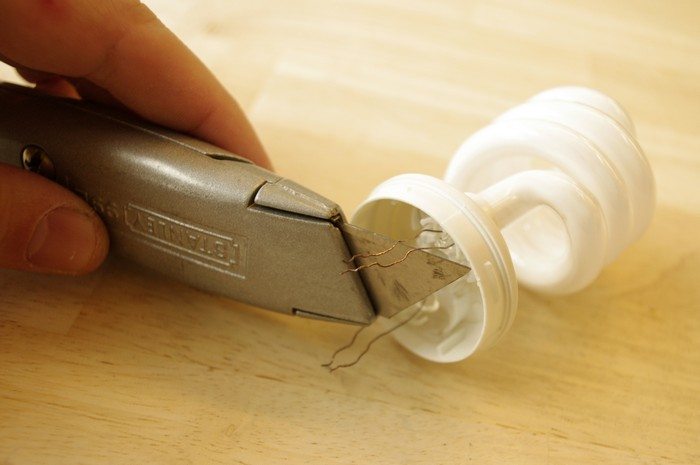
Prep the CFL Bulb: Scrape the coating off the wires coming out of the CFL bulb using a razor blade.
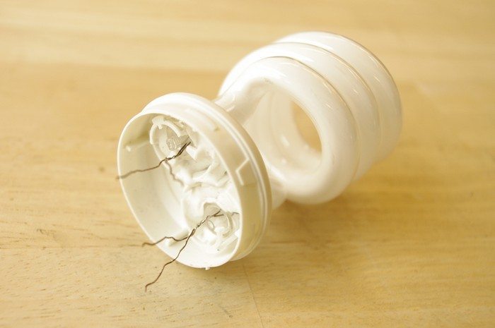
Twist the wires together and tin them with solder.
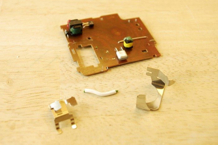
Remove extra parts: Remove any parts the stick out from the board such as battery terminals.
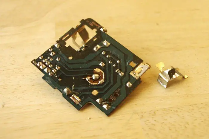
However, remember to make note of which terminals on the underside of the board they are connected to for future reference.
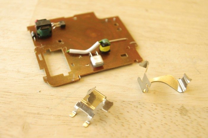
I also removed the wire connecting the top of the trigger transformer to the flash tube for the heck of it.
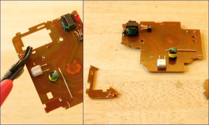
Trim the circuit board: Trim away any corners that have unnecessary electronic traces (or no traces at all).
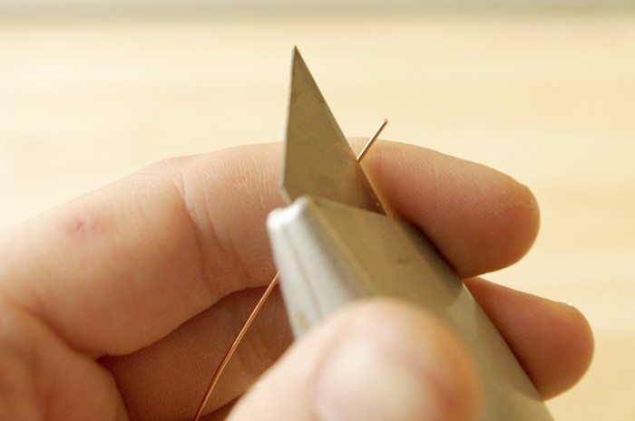
Prep the magnet wire: Strip away 1/2″ of plastic coating from both ends of two 3″ pieces of magnet wire using a razor blade.
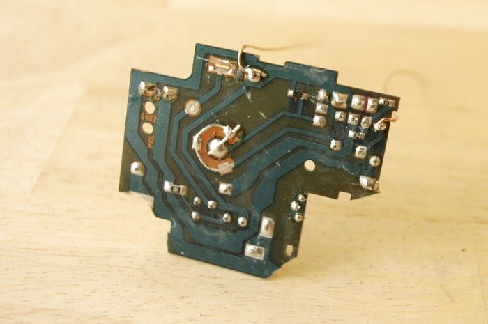
Hack a camera flash: Now is time to connect the wires to the board that will power the light.
Solder the first magnet wire to one of the terminals connected to the ground plane.
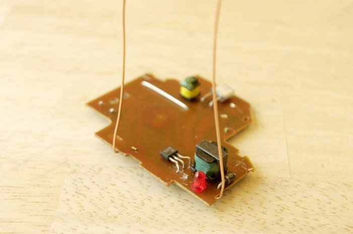
Solder the other wire to the terminal of the inverting transformer that the diode is connected to.
Note: If you are confused, a more hands on way of figuring this out is to use aligator clip jumper cables to connect the battery to the board. The board should now be live, so be careful of high voltages!
Using another cable, connect one of the bulbs leads to ground. Finally, connect a fourth cable to the other battery lead. Briefly touch this wire to various spots on the board until the bulb lights up. Once its lit, you have found the proper connection.
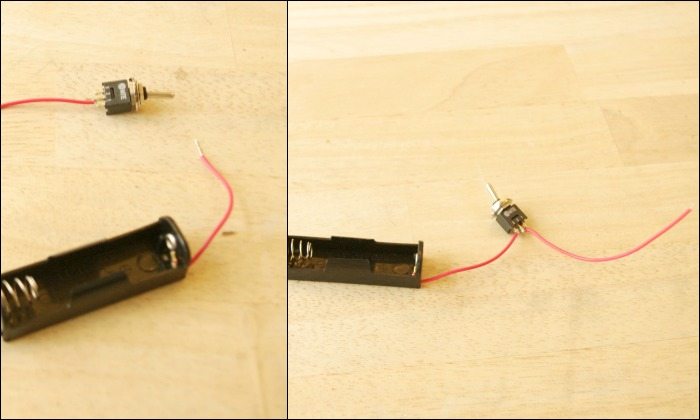
Connect to a switch: Trim the battery holder’s red wire in half. Solder the trimmed pieces to the center terminal of the switch and the red wire still connected to the battery holder to the switch’s outer terminal.
Continued Page 3…

