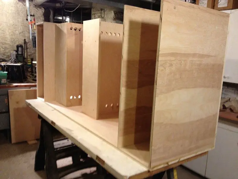
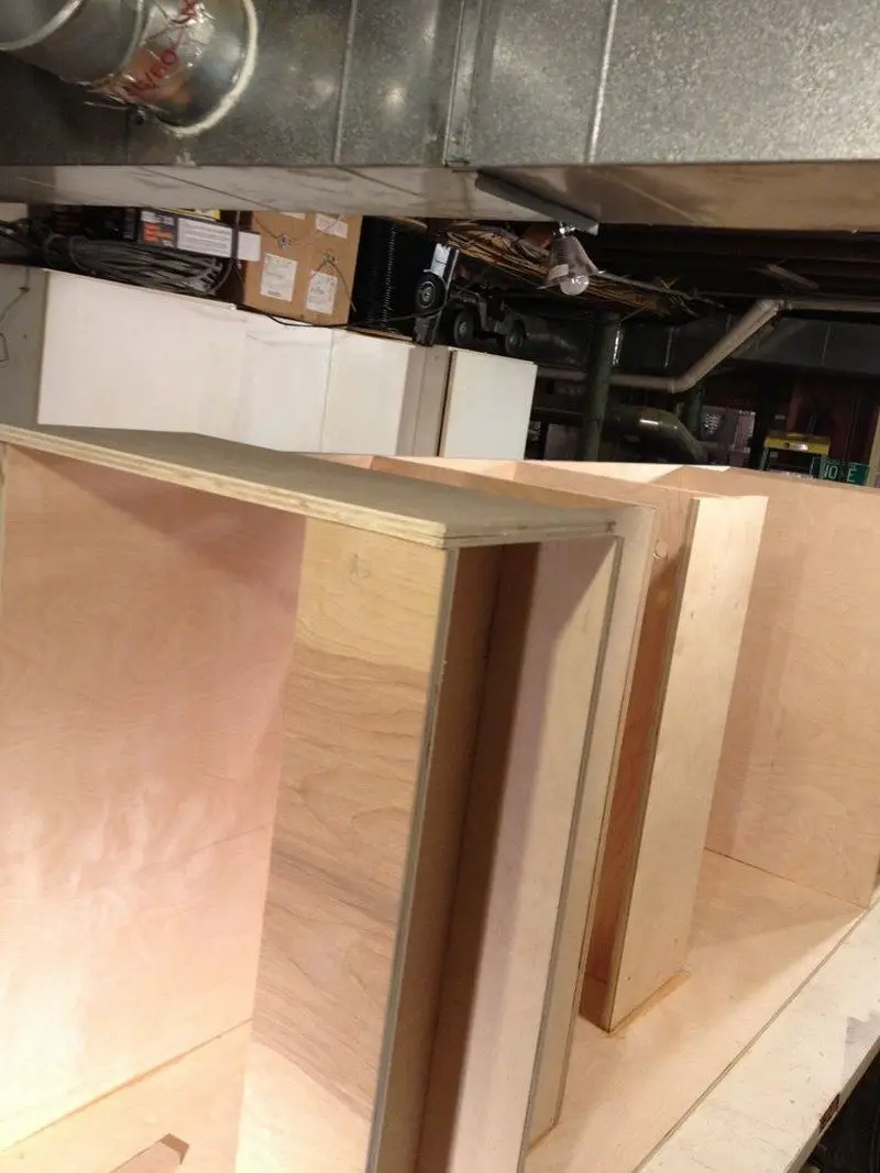
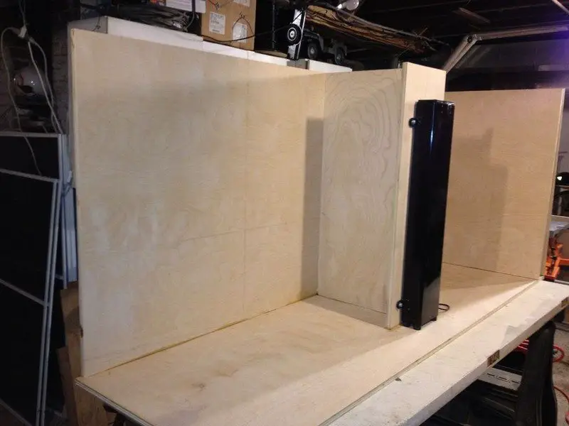
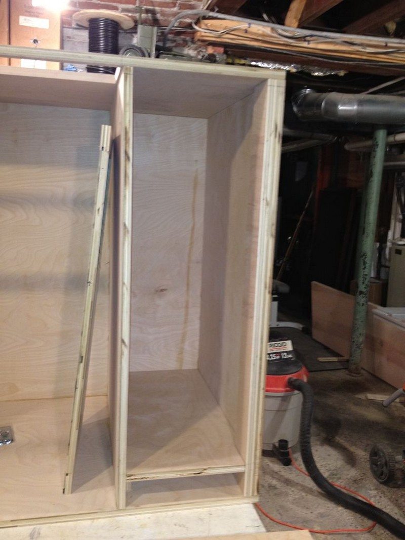
Continue adding the vertical members to the carcass of the TV lift cabinet. For reference, please see the top view drawing.
- Mark the inside back and bottom of the carcass with a line that is 11.5″ away from the right edge. Drill a few small holes 3/8″ to the left of this line on the inside back. Go to the back of the carcass and connect the holes with a straight edge to make a nailing line.
- Add glue to the top back and bottom of the piece “D”. Install it with the rightmost edge on the line you just marked so the inside dimension is exactly 11.5″. Go to the back and nail piece “D” in place.
- Go to the left side of the carcass and mark a line on the back that is 25″ in from the left-back edge. Drill holes 3/8″ over to the right of this line. Mark this line on the back. Mark another line 25 3/4″ over from the left side bottom edge.
- Put glue on the bottom and back of piece “B” and nail in from the back on the 25″ line.
- As shown in the drawing, draw a line 18.5″ parallel to the back.
- Put glue on the back and bottom of the “H” piece. As viewed from the left side of the carcass, it should attach to the right side of “B” and be on the right side of the 18.5″ line you drew. Nail from “B” into “H”.
- Put glue on the back and bottom of “A3”. Attach “A3” as shown in the diagram. Nail from the left side of “A3” into “H”.
- Put glue on the back and bottom of “A4”. Attach “A4″ as shown in diagram 10 7/8” from “A3”. Nail from the middle of “H” into “A4”.
- Add top panel support piece “FS”. It goes between pieces “B” and “D” as shown in the drawings. Apply glue to both ends of “FS”. Carefully nail into place from each end. Use clamps or a helper to get this right.
After the glue on the carcass dries, drill the holes for the lift and the vent holes. The glue should take a few hours to be rock solid.
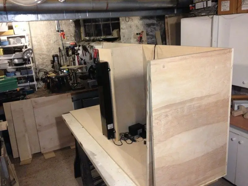
- Remove the top assembly from the Firgelli lift to make it a little lighter.
- Position the Firgelli to lift in the centre of “C1”. Mark the 4 holes with a pencil. Remove the Lift.
- Drill 4 holes as straight and accurately as you can.
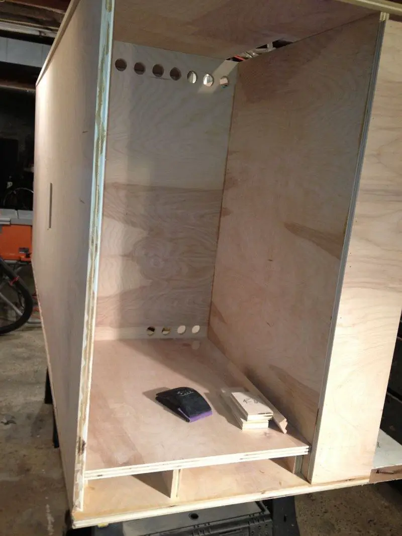
- Drill multiple vent holes with a 1″ bit as shown in the pictures below. These holes let component heat leave the left side component cabinet AND your wires and cables to pass around the TV lift cabinet.
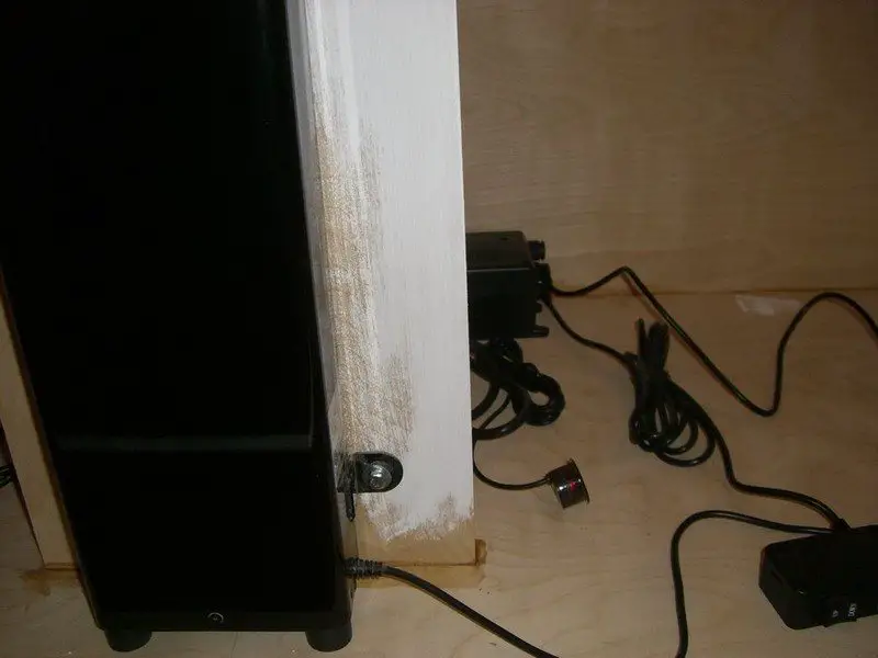
- Secure the lift to “C1” with nuts and bolts. Use a carriage bolt, nut, 2 smooth washers, and 2 lock washers on each hole.
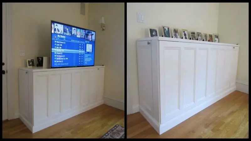
- Plug your lift and test its operation with the remote and manual switch.

Add the door carcass bottoms. Route HVAC air out the left door bottom but you may also not have to do this.
- Make 2 scrap piece templates that are 2 1/2″ wide by about 20″ long. These will be used to support the door bottoms while you glue and nail them. The idea is that the tops of these shelves will be at the top of “BB1” and “BB3” as shown in the drawing’s front and side views.
- Insert the two template pieces into the left door cavity. One next to the back and one next to piece “H”
- Put glue on the sides of the piece “A6”. Insert and nail in from the sides. Remove templates.
- Insert the two template pieces into the right door cavity. One next to the right side piece “E” and one next to piece “D”
- Put glue on the sides of the piece “E1”. Insert and nail in from the sides.
Continued Page 3…